Icm Head Pressure Control Wiring Diagram
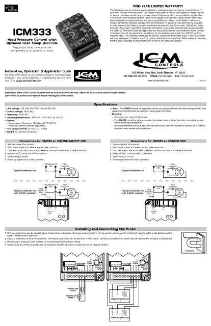
Icm333 Icm Controls
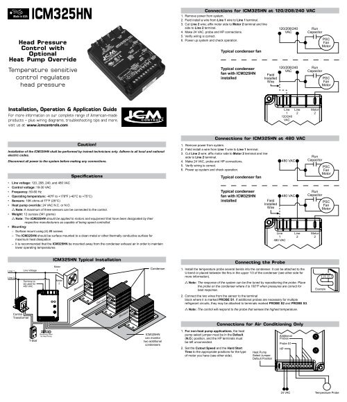
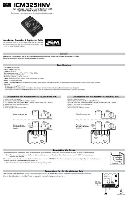
Icm325hn Icm Controls
Http Dms Hvacpartners Com Docs 1006 Public 0f 570 980 Pdf

Totaline Icm Controls Head Pressure Control Installation Youtube

Icm326hm2 Manualzz

Head Pressure Controller 2 Speed Fan Heating Help The Wall

With temperature and pressure inputs.
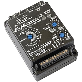
Icm head pressure control wiring diagram. Head pressure is regulated during low ambient conditions by varying the amount of airflow through the condenser. It can be attached to the. This helps ensure sufficient pressure across the expansion valve. Line voltage accessories.
The sensor probe should be mounted up several bends into the condenser upper 1 3 as shown at right to more closely monitor the condensing temperature. Install the temperature probe several bends into the condenser. Control circuitry line voltage this terminal to be ac icm325hn typical wiring diagram for systems with a contactor icm sensor probe mounting recommendations high efficiency systems. 35 465 psig solid state 10 amp load carrying capability eliminates overshoots common to on off and pressure switch controls helps prevent evaporator freeze ups low pressure cut outs and.
Hard start low temperature cutoff high temperature bypass isolated 24 vac supply is built into the control. 4 5 l x 3 w x 2 h. Helps prevent evaporator freeze ups low pressure cut outs and liquid slugged compressors in low ambient conditions. Direct set up from line voltage.
Integral heat pump bypass circuitry allows electonic bypass of speed control eliminates overshoots common to on off and pressure switch controls helps prevent evaporator freeze ups low pressure cut outs and liquid slugged compressors in low ambient conditions features. Fan coil relay controls. Hard start low temperature bypass isolated 24 vac supply rohs compliant lead free design controls up. Head pressure controls operate as temperature or pressure sensitive motor fan speed controls.
Installation Guide Icm Controls

7 3 Powerstroke Wiring Diagram Google Search With Images
66e95e Icm Head Pressure Control Wiring Diagram Wiring Library
Amazon Com Icm Controls Icm333 Low Ambient Head Pressure Control

Icm325hn Icm Controls Icm325hn Icm325hn Single Phase Head
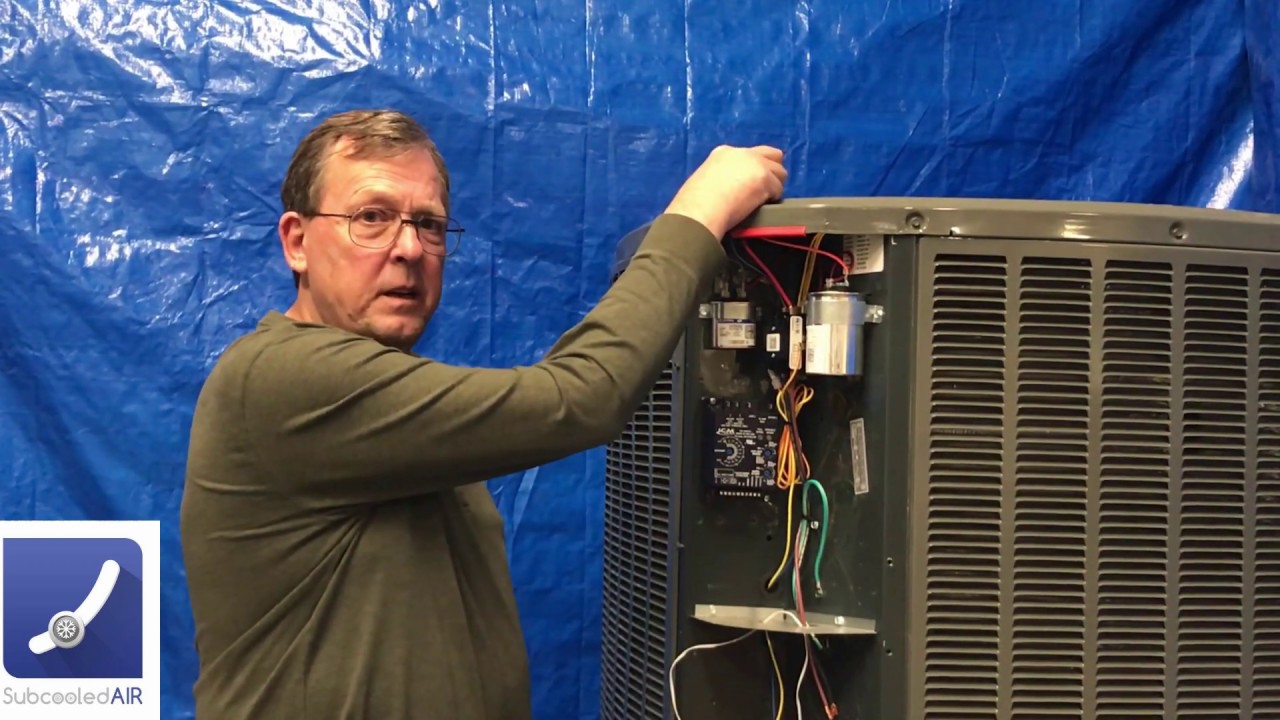
How To Install A Condenser Head Pressure Controller For Low

Pin By Rex Drogo On Back Cover Buick Century Buick Buick Lesabre

Pin On Diagnosis

Bard Compressor Control Module Ccm Sequence Of Operation Youtube

Distributorless Ignition System Dis Replaces The Distributor

Schematic Caterpillar 320d 336d Excavator Hydraulic System
Http Www Ductlessaire Com Wp Content Uploads 2019 08 13seer Service Pdf
