Icm Timer Wiring Diagram
Installation

How To Wire On Delay Timer
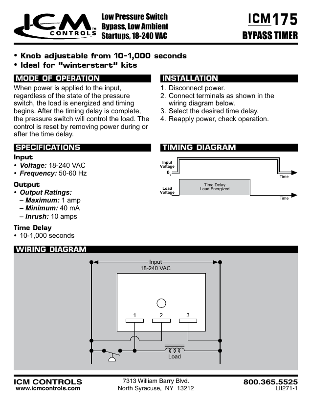
175 Icm Bypass Timer Manualzz
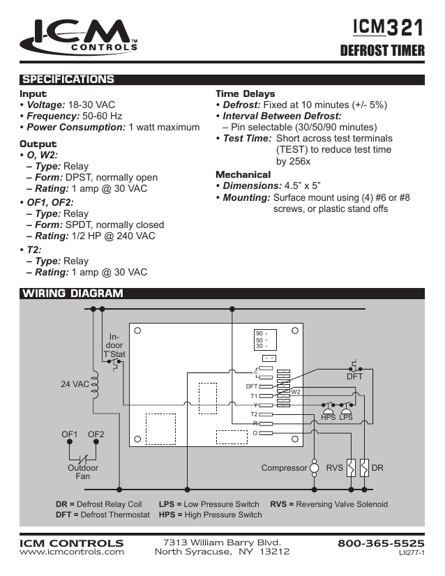
321 Icm Defrost Timer Manualzz
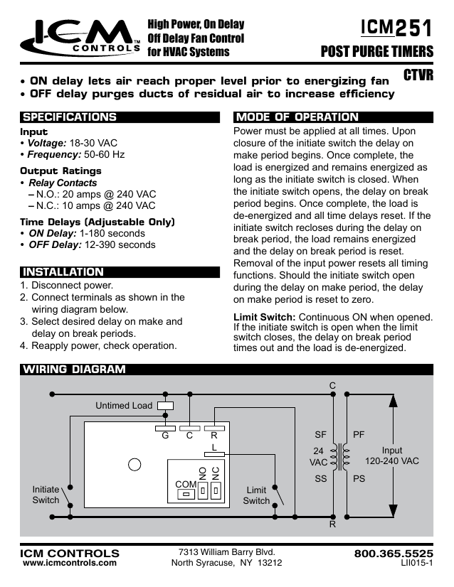
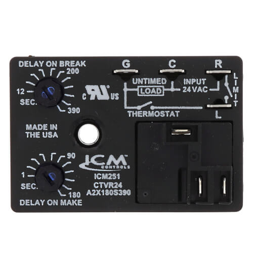
251 Icm Post Purge Timers Manualzz
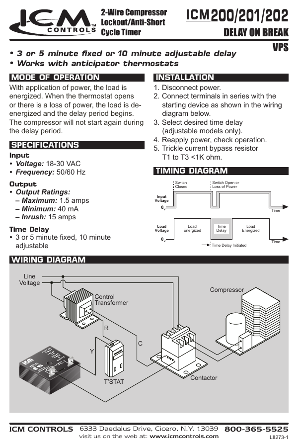
200 201 202 Icm Delay On Break Manualzz

This privacy policy tells you how we use personal information collected at this site.
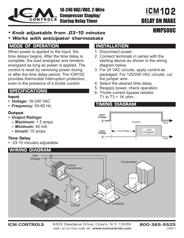
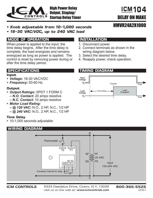
Icm timer wiring diagram. Delay icm102fb icm102f delay on make timer 6 wire leads 03 10 minute adj. Icm controls was granted an exemption from ny state s 100 workforce reduction mandate and remains operational. After the time delay is complete the load energizes. The delay turns off the load and resets the time delay to zero.
For the safety and well being of our employees we have made scheduling adjustments and other accommodations to help comply with ny state s social distancing policies pursuant to. North syracuse ny 13212 icm controls 800 365 5525. Designed to bypass a low pressure switch or other device during startup ideal for low ambient startups key component for winter start kits helps to reduce nuisance lockouts universal ac voltage operation knob adjustable time delays. Thank you for visiting our web site.
Delay on make timer with 03 10 minute adjustable delay universal 18 240 vac details. Delay on break timer with 03 10 minute adjustable time delay universal 18 240 vac details. It shows the components of the circuit as simplified shapes as well as the power as well as signal links in between the devices. Variety of intermatic 240v timer wiring diagram.
Icm102f delay on make timer 6 wire leads 03 10 minute adj. A one second interrogation delay is provided to avoid nuisance trips due to thermostat bounce or tampering. Universal voltage operation higher 1 5 amp power rating knob adjustable time delays works with anticipator type thermostats one model replaces many in field. Delay on make timers are ideal for compressor staging and stagger starting multiple motors and other equipment.
A wiring diagram is a simplified traditional pictorial representation of an electrical circuit. Timing diagram 3 or 5 minute fixed or 10 minute adjustable delay works with anticipator thermostats icm2 ˆ ˇ 0c4 m56 n 0 n 0 stal 0c4 m56 ˇ wiring diagram t stat contactor compressor control transformer line voltage 7313 william barry blvd. Compressor lockout anti short cycle timer helps to protect compressors from damage caused by rapid short cycling simple 2 wire hookup adjustable timing universal voltage. Wiring diagram control transformer line voltage fan t stat c r g 7313 william barry blvd.

Icm Relay Time Delay 4e233 Icm102 Grainger Timer Relay Delayed

Hvac Relay Training Bypass Timer Youtube
Icm Head Pressure Control Wiring Diagram Wiring Diagram

Icm Time Delay Relay Wiring Diagram Wiring Diagram
Icm Circuit Board Wiring Diagram Wiring Diagram
Icm251b Icm Controls Icm251b Icm251 Fan Blower Control Dual

24 Volt Programmable Timer

Icm254 Wiring Diagram Wiring Diagram
Rv Thermostat The Big Thermostat Info Page 100 Free
Icm272 Icm Controls Icm272 Icm272 Fan Blower Control Direct

Lennox 25g43 Time Delay Relay

Pin On Products
Icm Icm550 Defrost Control Timer Amazon Com
