Iec 9 Lead Delta Motor Wiring Diagram
Motor Wiring Part 2 Ec M

Electrical Delta Estrella With Images Electrical Projects

Bk 5075 Diagram Wye Connected Motor 9 Lead Wiring Diagram Dual
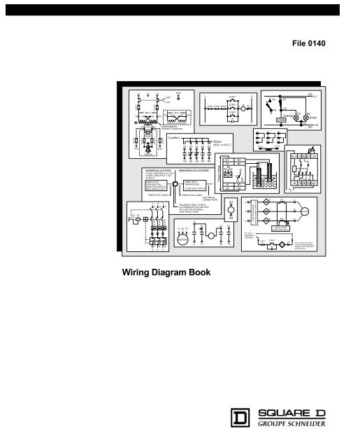
Wiring Diagram Book Schneider Electric
12 Lead Delta Motor Wiring Diagram Wiring Diagram

How To Convert A Basic Wiring Diagram To A Plc Program Youtube
Table 5 motor lead connections 64 table 6 enclosures for non hazardous locations 99 table 7 enclosures for hazardous locations 99 table 8 conductor ampacity100 table 9 ampacity correction factors 101 table 10 adjustment factors 101 table 11 ratings for 120 240 v 3 wire single phase dwelling services101 table 12 awg and metric wire data 102.
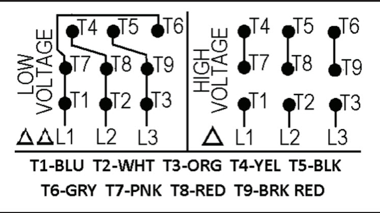
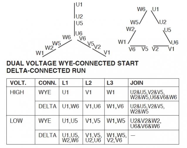
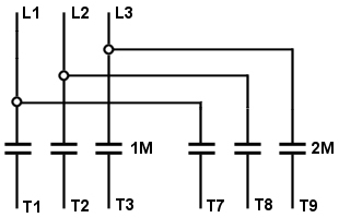
Iec 9 lead delta motor wiring diagram. Nema nomenclature 9 leads wye connected low voltage only t1 t2 t3 t7 t8 t9 together motor leads 1237894 5 6 nema and iec nomenclature 12 leads single voltage or low voltage of dual voltage motors t1 t2 t3 t7 t8 t9 nema 1 6 2 4 3 5 7 12 8 10 9 11 iec u1 w2 v1 u2 w1 v2 u5 w6 v5 u6 w5 v6 terminal markings and connections part winding start. Delta 6 leads per. Triple rate motor connection. Each lead may have one or more cables comprising that lead.
Determining wye or delta connection for motors on delta connected motor lead s 7 8 9 1 4 5 2 3 6 have continuity with. In such case each cable will be marked with the appropriate lead number. For the delta start dual voltage nine lead motor on the lower voltage connect 1 6 and 7 to l1. They are some times located in the peckerhead or junction box on the motor.
Three phase motor wire connections first read the nameplate for wiring instructions. Connect 2 4 and 8 to l2. The advantage of the iec twelve lead motor is that you can change connections from parallel to series and from star to delta. Delta connection single voltage with current transformers la sc.
Single voltage wye connected with partial current transformer protection. Three phase see below single voltage. Motor wiring diagram 9 lead dual voltage wye connection part winding start pws on low voltage to reverse direction of rotation interchange leads l1 l2. Mode tart run wye double delta extended delta 1 2 1 3 3 open together nema nomenclature 9 leads wye connected low voltage only motor leads 1 2 3 9 nema and ec nomenclature 12 leads single voltage or low voltage of dual voltage motors iec wi v5v2 vi nema iec 12 1 9 4 nema 31 wi v2 ui 85 vi u2 7 12 u5 w6 8 10 v5 u6 9 11.
Motor connection diagrams full lecture jim pytel. Delta connection 9 lead vt 2 speed 1 winding single voltage. For the higher voltage connect 1 to l1 2 to l2 and 3 to l3. If needed refer to the information below.
In a nema motor there are 12 leads or coil ends internally but only nine are brought out. Wye start delta run or pws connection 12 lead single voltage. 6 lead y 6 lead delta 9 lead high voltage y 9 lead low voltage y 9 lead high voltage delta 9 lead low voltage delta 12 lead high. Connect 3 5 and 9 to l3.

How To Control A Lamp Light Bulb From Two Places Using Two Way
Part Winding Start

Iec Motor 9 Post Wiring Diagram Wiring Diagram

Iec 9 Lead Delta Motor Wiring Diagram Wiring Diagram
Https Www Hollandindustrial Com Wp Content Uploads Sites 197 2015 12 European And American Motor Connections Pdf

Lathe Vfd 1 How To Wire A 3 Phase Motor And Vfd Youtube

3 Phase 6 Lead Motor Wiring Diagram Connections Wiring Diagram

Iveco Wiring Diagram
Https Www Toshiba Tips Co Jp En Products Motors Ckms 0702 Tdl Motor 2018 08 Pdf

6 Lead Wiring Diagram Wiring Diagram Data

Iec 9 Lead Delta Motor Wiring Diagram Kobe Balmoond19

Summary Of Ac Circuit Formula Electrical Engineering Blog

Wrg 2891 Toro Wiring Schematic