Ignition Module Wiring Ford Diagram Mallory

Mallory Distributor Wiring Diagram In 2020 With Images Diagram

Mb 9245 Mallory Ford Ignition Coil Wiring Diagram Schematic Wiring

Mallory Unilite Wiring Diagram Sbc Diagrams Schematics Inside
Ignition Module Ford Truck Enthusiasts Forums
How To Install An Msd 6a Digital Ignition Module On Your 1979 1995

Mallory Ignition Wiring Diagram Wiring Diagram

You can find the ignition control module test explained here.
Ignition module wiring ford diagram mallory. A wiring diagram is a simplified standard pictorial depiction of an electrical circuit. The purpose of an ignition ballast resistor between the ignition switch 12v and the ignition coil positive terminal is to restrict current flow through the ignition coil. Unilite distributor vacuum chamber and the carburetor. Ford ignition system circuit diagram 1994 1995 4 9l 5 0l and 5 8l.
If the vehicle is not originally equipped from the factory with an ignition ballast resistor or loom resistance wire a mallory ballast resistor pn 700 must be installed in series on the wire from the ignition switch to the. Wellborn collection of mallory ignition wiring diagram. September 29 2018 by larry a. In the next page you ll find the icm connector s pinout with a brief description of each wire.
The factory with an ignition ballast resistor or loom resistance wire from the ignition switch to the coil terminal. You can find the 1994 1995 ignition system wiring diagram here. Each component ought to be set and connected with different parts in specific way. It shows the components of the circuit as streamlined forms as well as the power and also signal links between the tools.
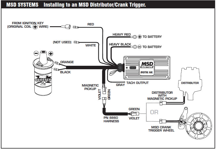
10 start the three wires of the mallory unilite module through the hole in the nose 14 route the wires from the unilite module to the ignition coil carefully 16 follow a factory shop manual to set the timing for your particular engine wiring diagram for mallory distributer don t worry if your coil doesn t look like this american one or. If not the structure won t function as it ought to be. To gray tach magnetic pickup not used pn 609. Coil to gray tach www street fire com pn 5520 multi spark n small red gm ignitions wiring an hei 5 or 7 pin module amplifier trigger.
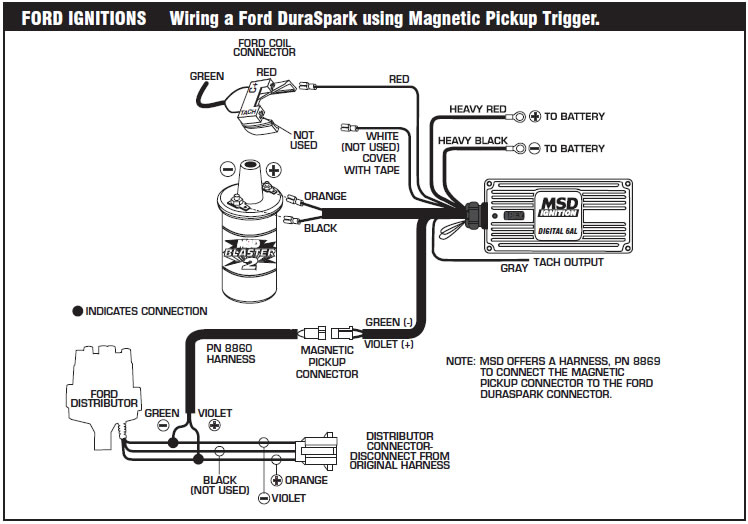
Mallory www mallory ignition com 915 857 5200 fax 915 857 3344 ford ignitions wiring a ford duraspark using white wire trigger.

Mallory Wiring Diagram 351 Wiring Diagram

La 3254 Mallory Unilite Distributor Wiring Diagram Schematic Wiring

Ignition Module Coil Poulan 2055 2075 2150 2175 222 262 S1838
Mallory Ignition Wiring Diagram 75 Wiring Diagram

Ad Ebay 8 Pc Denso Iridium Power Spark Plugs For Chevrolet G10
Mallory Wiring Diagram 351 Wiring Diagram

Mallory 29450 Ignition Coil Installation Instructions Jegs

Msd Wiring To Ford Tfi Style Ignition Foxbody F150 Ford Tfi
Mallory Ignition Wiring Diagram Vw Mk1 Wiring Diagram
Gm Points Style Ignition Distributor How To Wire And Run Diy Youtube

Cf 0756 Gm Hei 4 Pin Ignition Module Wiring Diagram Free Diagram

Aem Performance Electronics Map Sensor Auto Parts Online

Pin On Ignition Systems Car And Truck Parts
